rfid tag circuit pdf Typical RFID tag with a T-matched antenna. Tag performance can be characterized by tag . Each vehicle has its own ECDH key which it sends to the card to authenticate, along with a 128-bit random challenge. The card responds with a 128-bit response to complete the .
0 · rfid design
1 · rfid antenna technology
2 · rfid antenna size chart
3 · rfid antenna design PDF
4 · rfid antenna circuit size
5 · rfid antenna circuit diagram
6 · rfid antenna circuit design
7 · antenna circuit design PDF
Dallas Cowboys 3-5 (third place, NFC East) The Bears' once-strong wild-card aspirations took a hit in Week 9, while the Buccaneers' key injury issues can continue to .
Typical RFID tag with a T-matched antenna. Tag performance can be characterized by tag .The efficient transfer of energy from the reader to the tag directly affects operational reliability .
When it comes to the tag and reader antennas for the RFID, designers adopt the concept .

Radio Frequency Identification (RFID) systems use radio frequency to identify, locate and track .This section is written for RF coil designers and RFID system engineers. It reviews basic electromagnetic theories on antenna coils, a procedure for coil design, calculation and measurement of inductance, an antenna tuning method, and read range in RFID applications. 2003 Microchip Technology Inc.
Typical RFID tag with a T-matched antenna. Tag performance can be characterized by tag sensitivity (also called threshold POTF, Power on Tag Forward) and tag backscatter (also called POTR, Power on Tag Reverse). A typical response of a T-matched tag is shown in Fig. 2 where both POTF and POTR are at tag threshold.The efficient transfer of energy from the reader to the tag directly affects operational reliability and read/write range. Generally, both 13.56 MHz and 125 kHz RFID tags use parallel resonant LC loop antennas, tuned to the carrier frequency. This application note gives an overview of basic tag antenna tuning.
rfid design
When it comes to the tag and reader antennas for the RFID, designers adopt the concept imitating the radar technology in which the re ader transmits a signal to a tag and the tag sends back its recorded data to the reader.

Radio Frequency Identification (RFID) systems use radio frequency to identify, locate and track people, assets and animals. Passive RFID systems are composed of three components – a reader (interroga-tor), passive tag and host computer. The tag is com-posed of an antenna coil and a silicon chip that includes basic modulation circuitry and non .In this paper, we explain how to design a UHF tag antenna for ARC specs, including modeling and simulation of tag antennas using standard dielectric materials that can be used to approximately model the effect of ARC items on RFID tags. TABLE I. TABLE OF ARC SPECS, IN DBM (POTF AND POTR). Band.
Radio Frequency Identification (RFID) is the most reliable way to electronically identify, data capture, control, track, and inventory items using RF communication. Today RFID is ubiquitous having a very broad use but most of the time such systems are .
Abstract—In this work, we present a simple open-source software-defined based UHF (RAIN) RFID tag that can be used for academic research. This work is a follow-up to the open- source reader work presented in [1]. The hardware associated with this tag is only composed of an envelope detector and an RF switch and uses a modular design.
rfid antenna technology
Introduction. The ST25 NFC (near field communication) and RFID (radio frequency identification) tags extract their power from the reader field. The tag and reader antennas are inductances mutually coupled by the magnetic field, similarly to a voltage transformer (see Figure 1).
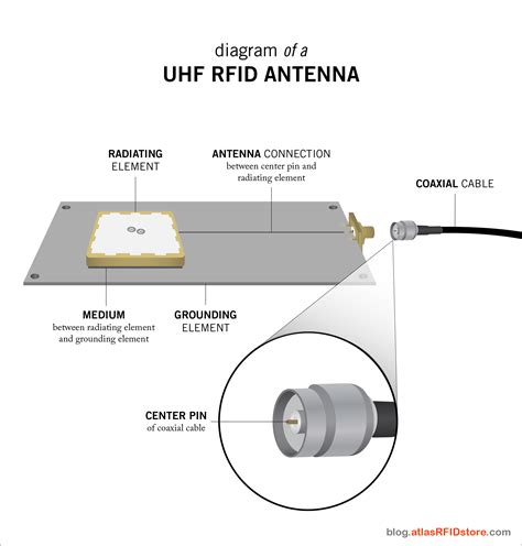
Tags consist of a silicon device and antenna circuit. The purpose of the antenna circuit is to induce an energizing signal and to send a modulated RF signal. The read range of a tag largely depends upon the antenna circuit and size. The antenna circuit is made of a LC resonant circuit or E-field dipole antenna, depending on the carrier frequency.This section is written for RF coil designers and RFID system engineers. It reviews basic electromagnetic theories on antenna coils, a procedure for coil design, calculation and measurement of inductance, an antenna tuning method, and read range in RFID applications. 2003 Microchip Technology Inc.
Typical RFID tag with a T-matched antenna. Tag performance can be characterized by tag sensitivity (also called threshold POTF, Power on Tag Forward) and tag backscatter (also called POTR, Power on Tag Reverse). A typical response of a T-matched tag is shown in Fig. 2 where both POTF and POTR are at tag threshold.The efficient transfer of energy from the reader to the tag directly affects operational reliability and read/write range. Generally, both 13.56 MHz and 125 kHz RFID tags use parallel resonant LC loop antennas, tuned to the carrier frequency. This application note gives an overview of basic tag antenna tuning.
When it comes to the tag and reader antennas for the RFID, designers adopt the concept imitating the radar technology in which the re ader transmits a signal to a tag and the tag sends back its recorded data to the reader.Radio Frequency Identification (RFID) systems use radio frequency to identify, locate and track people, assets and animals. Passive RFID systems are composed of three components – a reader (interroga-tor), passive tag and host computer. The tag is com-posed of an antenna coil and a silicon chip that includes basic modulation circuitry and non .
In this paper, we explain how to design a UHF tag antenna for ARC specs, including modeling and simulation of tag antennas using standard dielectric materials that can be used to approximately model the effect of ARC items on RFID tags. TABLE I. TABLE OF ARC SPECS, IN DBM (POTF AND POTR). Band.Radio Frequency Identification (RFID) is the most reliable way to electronically identify, data capture, control, track, and inventory items using RF communication. Today RFID is ubiquitous having a very broad use but most of the time such systems are .Abstract—In this work, we present a simple open-source software-defined based UHF (RAIN) RFID tag that can be used for academic research. This work is a follow-up to the open- source reader work presented in [1]. The hardware associated with this tag is only composed of an envelope detector and an RF switch and uses a modular design.Introduction. The ST25 NFC (near field communication) and RFID (radio frequency identification) tags extract their power from the reader field. The tag and reader antennas are inductances mutually coupled by the magnetic field, similarly to a voltage transformer (see Figure 1).
rfid antenna size chart

an rfid reader rfid interrogator is
albrint front pocket minimalist wallet rfid leather slim card holder
Download. 3.0 on 16 votes. The ACR122U NFC Reader is a PC-linked contactless smart card reader/writer developed based on the 13. NFC CSP. Download. NFC Connector is a solution to emulate cryptographic smart card .
rfid tag circuit pdf|rfid antenna circuit size