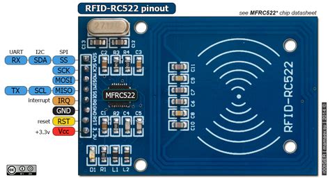
rfid tag pin diagram Learn how to use RFID NFC RC522 with Arduino, how to connect RFID-RC522 module to Arduino, how to code for RFID/NFC, how to program Arduino step by step. The detail .
Method 2: Looking for signs on the card: Some cards may have visible .The truth? The computer chips in EMV cards don't send out radio frequency signals at all. The companies selling wireless-blocking sleeves are actually selling products that will protect consumers against an entirely different technology. A few years back, credit-card companies were pushing credit cards that allowed . See more
0 · rfid reader module pinout
1 · rfid examples arduino
2 · rfid arduino project
3 · arduino rfid settings
4 · arduino rfid pin
5 · arduino rfid module pinout
6 · arduino rfid module connection
7 · arduino rfid input
Watch on. The Steps: 1: Plug in you NFC reader/writer into the port on your computer. There should be a light on it that lights up red. When putting an NFC item on the platform the unit should beep and the light should turn green, .
In this module, there are only two kinds of pins. So, the first one is power and the second one is the communication pins. Therefore, the device may have its microcontroller chip on itself but it only makes it to works as an RFID. The onboard microcontroller won’t make the module a stand-alone device. See more
The RC 522 usage is simple and complex at the same time. Even its library has too much complexity to understand. First, understand that library examples and documentation are . See more
The RC522 is a 13.56MHz RFID module that is based on the MFRC522 controller from NXP semiconductors. The module can supports I2C, SPI and UART and normally is shipped with a RFID card and key fob. It is .RC522 RFID Reader Module Pinout diagram, Pin Configuration details, Interfacing with Arduino Example, Applications, Features, Datasheet. The RC522 is a 13.56MHz RFID module that is based on the MFRC522 controller from NXP semiconductors. The module can supports I2C, SPI and UART and normally is .
Learn how to use RFID NFC RC522 with Arduino, how to connect RFID-RC522 module to Arduino, how to code for RFID/NFC, how to program Arduino step by step. The detail .An RFID or radio frequency identification system consists of two main components, a tag attached to the object to be identified, and a reader that reads the tag. A reader consists of a radio . Learn how to use the RFID RC522 module with Arduino for access control. Step-by-step guide, practical applications, and sample code included.Learn how to interfacing RFID Reader with Arduino. Reading RFID tags and giving access. RFID pinout, Circuit, Code for RFID with Arduino
rfid reader module pinout
RFID RC522 Reader Module. RFID card tag and key fob. The RC522 module works on a 13.56 MHz frequency and it can act as a reader and write for UID/RFID cards. The RFID cards . RC522 RFID Module Basics. The MFRC522 is a 13.56 MHz RFID (Radio-frequency identification) IC. The RC522 reader supports ISO/IEC 14443 A/MIFARE and NTAG. But anyways, today, I will explain the very basic things that will help you to easily get started with the Arduino and MFRC522 RFID Module. In this article, I will explain, the .
rfid examples arduino
The reader can communicate with any microcontroller through four wires SPI interface. RFID reader also supports I2C and UART interfaces. There is an interrupt pin in the .RC522 RFID Reader Module Pinout diagram, Pin Configuration details, Interfacing with Arduino Example, Applications, Features, Datasheet.
The RC522 is a 13.56MHz RFID module that is based on the MFRC522 controller from NXP semiconductors. The module can supports I2C, SPI and UART and normally is .Learn how to use RFID NFC RC522 with Arduino, how to connect RFID-RC522 module to Arduino, how to code for RFID/NFC, how to program Arduino step by step. The detail .
An RFID or radio frequency identification system consists of two main components, a tag attached to the object to be identified, and a reader that reads the tag. A reader consists of a radio . Learn how to use the RFID RC522 module with Arduino for access control. Step-by-step guide, practical applications, and sample code included.Learn how to interfacing RFID Reader with Arduino. Reading RFID tags and giving access. RFID pinout, Circuit, Code for RFID with Arduino
RFID RC522 Reader Module. RFID card tag and key fob. The RC522 module works on a 13.56 MHz frequency and it can act as a reader and write for UID/RFID cards. The RFID cards . RC522 RFID Module Basics. The MFRC522 is a 13.56 MHz RFID (Radio-frequency identification) IC. The RC522 reader supports ISO/IEC 14443 A/MIFARE and NTAG. But anyways, today, I will explain the very basic things that will help you to easily get started with the Arduino and MFRC522 RFID Module. In this article, I will explain, the .

how far away can rfid readers work
rfid arduino project
Information. NFC Tools GUI is a cross Platform software : it works on Mac, Windows and Linux. You can read and write your NFC chips with a simple and lightweight user interface. Connect your NFC reader to your computer like the .
rfid tag pin diagram|arduino rfid input