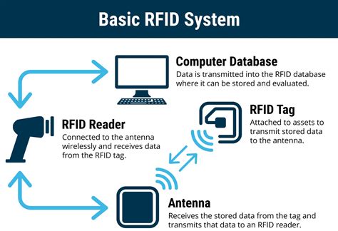
rfid tag diagram Once you understand the information above, you will need three things in order to program RFID tags - an RFID reader with an antenna, software to control the reader, and Passive UHF RFID tags. Today I’m going to walk through two options for a low cost and simple hardware and software solution.
$126.00
0 · rfid tag reader basics
1 · rfid tag generator
2 · make your own rfid tags
3 · how to read rfid tags
4 · how to create rfid tags
5 · explain transponder with block diagram
6 · block diagram of rfid tag
7 · block diagram of rfid system
Twitter: https://twitter.com/All_HighlytesInstagram: https://www.instagram.com/all_highlytesBusiness Email: [email protected] rights go to ABC, .
A well-designed schematic diagram of an RFID tag offers a detailed view of how .A simplified block schematic of an RFID tag (also called transponder) is shown in the diagram . A well-designed schematic diagram of an RFID tag offers a detailed view of how the tag works and what kind of information it can provide. It includes a circuit board, antennas, RF receivers and transmitters, power sources, and interface ports.RFID uses radio waves produced by a reader to detect the presence of (then read the data stored on) an RFID tag. Tags are embedded in small items like cards, buttons, or tiny capsules.
A simplified block schematic of an RFID tag (also called transponder) is shown in the diagram below. Various components of the tag are as shown. Normally, the antenna is external to the tag chip, and large in size. Once you understand the information above, you will need three things in order to program RFID tags - an RFID reader with an antenna, software to control the reader, and Passive UHF RFID tags. Today I’m going to walk through two options for a low cost and simple hardware and software solution. RFID technology offers a powerful and versatile tool for tracking and managing assets. By understanding the core principles behind passive and active tags, communication protocols, manufacturing processes, and factors influencing read range and frequency, you can make informed decisions when deploying RFID solutions in your projects. RFID (Radio Frequency Identification) is a technology that uses electromagnetic fields to automatically identify and track tags attached to objects. These tags contain electronically stored information that can be read from several meters away, without requiring direct line-of .

Learn the different components that go into an RFID Tag such as RFID chip, inlay, antenna and strap. Choosing the best RFID is important for any RFID project.Radio Frequency Identification (RFID) is the most reliable way to electronically identify, data capture, control, track, and inventory items using RF communication. Today RFID is ubiquitous having a very broad use but most of the time such systems are .Since the energizing and communication between the reader and tag is accomplished through antenna coils, it is important that the device must be equipped with a proper antenna circuit for successful RFID applications.In this tutorial, we learn how to interfacing RFID with an Arduino. An RFID Sensor, which is a Radio Frequency Identification Reader, gathers data from a card with an RFID tag.
A well-designed schematic diagram of an RFID tag offers a detailed view of how the tag works and what kind of information it can provide. It includes a circuit board, antennas, RF receivers and transmitters, power sources, and interface ports.RFID uses radio waves produced by a reader to detect the presence of (then read the data stored on) an RFID tag. Tags are embedded in small items like cards, buttons, or tiny capsules.
A simplified block schematic of an RFID tag (also called transponder) is shown in the diagram below. Various components of the tag are as shown. Normally, the antenna is external to the tag chip, and large in size. Once you understand the information above, you will need three things in order to program RFID tags - an RFID reader with an antenna, software to control the reader, and Passive UHF RFID tags. Today I’m going to walk through two options for a low cost and simple hardware and software solution. RFID technology offers a powerful and versatile tool for tracking and managing assets. By understanding the core principles behind passive and active tags, communication protocols, manufacturing processes, and factors influencing read range and frequency, you can make informed decisions when deploying RFID solutions in your projects. RFID (Radio Frequency Identification) is a technology that uses electromagnetic fields to automatically identify and track tags attached to objects. These tags contain electronically stored information that can be read from several meters away, without requiring direct line-of .
Learn the different components that go into an RFID Tag such as RFID chip, inlay, antenna and strap. Choosing the best RFID is important for any RFID project.Radio Frequency Identification (RFID) is the most reliable way to electronically identify, data capture, control, track, and inventory items using RF communication. Today RFID is ubiquitous having a very broad use but most of the time such systems are .Since the energizing and communication between the reader and tag is accomplished through antenna coils, it is important that the device must be equipped with a proper antenna circuit for successful RFID applications.
why do modern smart phones not have memory cards
rfid tag reader basics
rfid tag generator
make your own rfid tags

If you have any questions or comments for us, please fill out the form below with all .
rfid tag diagram|block diagram of rfid system