passive rfid tag breadboard RFID tags come in different forms, including passive, active, and semi-passive tags. Passive tags do not have an internal power source and rely on the energy received from the reader to operate. Active tags have their own power . List from much groups ,forumss etc. The bigest list bins NON VBV / AUTO VBV .
0 · rfid with access control
1 · rfid tag diagram
2 · how to make rfid tags
3 · arduino rfid tag diagram
4 · arduino rfid
Near-field communication (NFC) is a short-range wireless connectivity technology that uses .
rfid with access control
The RFID RC522 module can be used in various practical applications, including: Access Control Systems: Secure your home or office by granting access only to authorized RFID tags. Attendance Systems: Track . RFID tags come in different forms, including passive, active, and semi-passive tags. Passive tags do not have an internal power source and rely on the energy received from the reader to operate. Active tags have their own .

my contactless card wont work barclays
The RFID RC522 module can be used in various practical applications, including: Access Control Systems: Secure your home or office by granting access only to authorized RFID tags. Attendance Systems: Track employee or student attendance by scanning RFID cards. RFID tags come in different forms, including passive, active, and semi-passive tags. Passive tags do not have an internal power source and rely on the energy received from the reader to operate. Active tags have their own power .Passive RFID tags harness energy from an RFID reader’s emitted Radio-frequency (RF) signal. When the reader sends a signal, it creates an electromagnetic field that energizes the tag. The tag captures this energy and powers its internal chip, enabling it to transmit data back to the reader.
In a passive RFID system, the reader will have an antenna that will emit RF energy that will induce a current in the tag’s circuitry. So whenever the tag is moving through the reader’s electromagnetic field, it gets powered and then immediately broadcasts its unique code. Passive RFID tags, characterized by their cost-effectiveness and versatility, present scalability advantages for organizations seeking to deploy RFID technology across diverse assets and inventory items.
In this tutorial series, passive, high frequency (13.56 MHz) RFID tags are the focus, as they are very compact, inexpensive, and require no external battery power. Passive RFID. A passive RFID system has an antenna and circuitry that houses a unique code, but has no power source. A passive RFID system requires a reader to induce current into the RFID tag’s circuitry, similar to how the . To read the Passive RFID cards and tag, we need a microcontroller with UART hardware. If we select a microcontroller without UART, we need to implement software UART. Here we are using PIC Microcontroller PIC16F877A for interfacing RFID. We will simply read the unique identification no. of RFID tags and display it on 16x2 LCD.
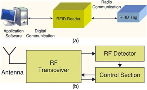
Passive RFID systems are composed of three components – an interrogator (reader), a passive tag, and a host computer. The tag is composed of an antenna coil and a silicon chip that includes basic modulation circuitry and non-volatile memory.Passive RFID tags contain a low-power integrated circuit (IC) attached to an antenna, and are enclosed with pro-tective packaging (like a plastic card) as determined by the application. On-board memory within the IC stores data. The IC then transmits/receives information through the antenna to an external reader, called an interroga-tor. The RFID RC522 module can be used in various practical applications, including: Access Control Systems: Secure your home or office by granting access only to authorized RFID tags. Attendance Systems: Track employee or student attendance by scanning RFID cards. RFID tags come in different forms, including passive, active, and semi-passive tags. Passive tags do not have an internal power source and rely on the energy received from the reader to operate. Active tags have their own power .
Passive RFID tags harness energy from an RFID reader’s emitted Radio-frequency (RF) signal. When the reader sends a signal, it creates an electromagnetic field that energizes the tag. The tag captures this energy and powers its internal chip, enabling it to transmit data back to the reader. In a passive RFID system, the reader will have an antenna that will emit RF energy that will induce a current in the tag’s circuitry. So whenever the tag is moving through the reader’s electromagnetic field, it gets powered and then immediately broadcasts its unique code. Passive RFID tags, characterized by their cost-effectiveness and versatility, present scalability advantages for organizations seeking to deploy RFID technology across diverse assets and inventory items. In this tutorial series, passive, high frequency (13.56 MHz) RFID tags are the focus, as they are very compact, inexpensive, and require no external battery power.
Passive RFID. A passive RFID system has an antenna and circuitry that houses a unique code, but has no power source. A passive RFID system requires a reader to induce current into the RFID tag’s circuitry, similar to how the . To read the Passive RFID cards and tag, we need a microcontroller with UART hardware. If we select a microcontroller without UART, we need to implement software UART. Here we are using PIC Microcontroller PIC16F877A for interfacing RFID. We will simply read the unique identification no. of RFID tags and display it on 16x2 LCD.Passive RFID systems are composed of three components – an interrogator (reader), a passive tag, and a host computer. The tag is composed of an antenna coil and a silicon chip that includes basic modulation circuitry and non-volatile memory.
rfid tag diagram
how to make rfid tags
natwest bank card contactless
arduino rfid tag diagram

TIL: You can use old credit cards as NFC tags. Don't know why I never thought .
passive rfid tag breadboard|arduino rfid tag diagram