rfid reader with serial interface The Schematic diagram for the RC522 moduleis given below. The circuit consists of bare minimum components. As we know the main component is the MFRC522 chip. The remaining components form the EMI filter along with the matching circuit . See more Use an iPhone as an NFC Tag Reader. iPhone uses two types of NFC scanning, In-App Tag Reading (the user manually scans the NFC tag) and Background Tag Reading (the iPhone automatically scans for the NFC tags in .
0 · rfid serial number
1 · rfid reader serial port
2 · rfid reader code
3 · rfid reader circuit diagram
4 · rfid reader arduino code
5 · rfid card reader code
6 · code to check rfid chip
7 · 12c rfid on arduino
PHYSICAL ADDRESS 137 South Gay Street, Auburn, AL 36830 MAILING .
rfid serial number
The RC522 module has a total of 8 pins. This module supports various communication protocols and each pin has a different function for each communication protocol. The pinout of a RFID Reader moduleis as follows: SDA SCLI2C Communication pins. DATA and CLOCK. SS SCK MOSI . See moreThe Schematic diagram for the RC522 moduleis given below. The circuit consists of bare minimum components. As we know the main component is the MFRC522 chip. The remaining components form the EMI filter along with the matching circuit . See more
rfid reader serial port
What is an RFID used for? RFID tags are a type of tracking system that uses radiofrequency to search, identify, track, and communicate . See more
The RC522 RFID module is based on the popular MFRC522 RFID reader chip from NXP These modules are cheap and available from most . See more
The RFID system is comprised of two components: the RFID reader and the tags. They are also called PCD (Proximity Coupling Device) and PICC (Proximity Integrated Circuit . See more
The RC522 RFID reader module is designed to create a 13.56MHz electromagnetic field and communicate with RFID tags (ISO 14443A standard tags). The reader can communicate with .
The MFRC522 supports three different communication protocols: SPI with Speed up to 10Mbit/s. I2C interface with speed up to 400kBd in Fast mode and up to 3400kBd in High-Speed mode. RS232 Serial UART with speed up to 1228.8kBd. The RC522 module usually comes with an RFID card and a key fob.The RC522 RFID reader module is designed to create a 13.56MHz electromagnetic field and communicate with RFID tags (ISO 14443A standard tags). The reader can communicate with a microcontroller over a 4-pin SPI with a maximum data rate of 10 Mbps.
Learn to interface RFID reader RDM6300 RDM630 modules with Arduino, examples to read RFID number from cards and display on serial monitor
rfid reader code
RFID RC522 Reader Module. RFID card tag and key fob. The RC522 module works on a 13.56 MHz frequency and it can act as a reader and write for UID/RFID cards. The RFID cards communicate with the module at a short distance with radio .In this tutorial, we are going to learn how to use RFID/NFC with Arduino. The RFID/NFC system includes two components: reader and tag. There are two popular RFID/NFC readers: RC522 and PN532 RFID/NFC reader. This tutorial focuses on RC522 RFID/NFC reader.Hai there in this tutorial i'm going to help you with interfacing RFID-RC522 with Arduino Mega 2560 to read the RFID and Display the Data on the Serial Monitor. so you can able to extend it on your own. You Need: Arduino Mega or Arduino Uno (I used Mega) RFID-RC522; 7 male to female jumper wires; Some ID cards (optional) RFID Library (Must . The RC522 RFID Reader Module is designed to create 13.56MHz electromagnetic fields that it uses for communication with RFID tags (ISO 14443A standards tags). The 4-pin Serial Perimeter Interface allows the reader to communicate with a microcontroller.

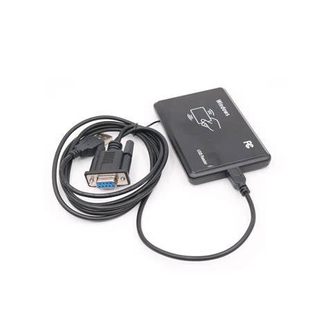
RFID reader puts this unique ID data in the form of bytes on serial Tx pins. This data can be used by the microcontroller serially using UART communication.2400 baud serial interface. Enable input allows module to be enabled/disabled by software. Bi-color LED for visual indication of status. Application Ideas: Robotics. Payment Systems. Automatic Identification. RFID Card Reader Details: Reads 125 kHz Tags, EM4100 Family. Power requirements: 4.5 to 5.5 VDC. Communication: Serial at 2400 baud (8N1)Step 1: Parts List. 1.1 x Arduino UNO. 2.1 x Integrated UHF reader LSID-0702. 3.1 x serial DB9 cable. 4.1 x Rs232 shield. 5.1 x UHF RFID tag. Step 2: Wire Diagram. Install RS232 Shield v2 on Arduino, and connect the DB9 of RS232 shield to the DB9 connector of the RFID reader, and supply power to the integrated RFID reader.
The MFRC522 supports three different communication protocols: SPI with Speed up to 10Mbit/s. I2C interface with speed up to 400kBd in Fast mode and up to 3400kBd in High-Speed mode. RS232 Serial UART with speed up to 1228.8kBd. The RC522 module usually comes with an RFID card and a key fob.
The RC522 RFID reader module is designed to create a 13.56MHz electromagnetic field and communicate with RFID tags (ISO 14443A standard tags). The reader can communicate with a microcontroller over a 4-pin SPI with a maximum data rate of 10 Mbps.
Learn to interface RFID reader RDM6300 RDM630 modules with Arduino, examples to read RFID number from cards and display on serial monitorRFID RC522 Reader Module. RFID card tag and key fob. The RC522 module works on a 13.56 MHz frequency and it can act as a reader and write for UID/RFID cards. The RFID cards communicate with the module at a short distance with radio .In this tutorial, we are going to learn how to use RFID/NFC with Arduino. The RFID/NFC system includes two components: reader and tag. There are two popular RFID/NFC readers: RC522 and PN532 RFID/NFC reader. This tutorial focuses on RC522 RFID/NFC reader.Hai there in this tutorial i'm going to help you with interfacing RFID-RC522 with Arduino Mega 2560 to read the RFID and Display the Data on the Serial Monitor. so you can able to extend it on your own. You Need: Arduino Mega or Arduino Uno (I used Mega) RFID-RC522; 7 male to female jumper wires; Some ID cards (optional) RFID Library (Must .
The RC522 RFID Reader Module is designed to create 13.56MHz electromagnetic fields that it uses for communication with RFID tags (ISO 14443A standards tags). The 4-pin Serial Perimeter Interface allows the reader to communicate with a microcontroller. RFID reader puts this unique ID data in the form of bytes on serial Tx pins. This data can be used by the microcontroller serially using UART communication.
2400 baud serial interface. Enable input allows module to be enabled/disabled by software. Bi-color LED for visual indication of status. Application Ideas: Robotics. Payment Systems. Automatic Identification. RFID Card Reader Details: Reads 125 kHz Tags, EM4100 Family. Power requirements: 4.5 to 5.5 VDC. Communication: Serial at 2400 baud (8N1)
nfc contact sharing

rfid reader circuit diagram
rfid reader arduino code
rfid card reader code
Campbell becomes the third football radio analyst over the last 43 years for Auburn, joining White (2001-22) and former Auburn signal caller Charlie Trotman (1980-2000). In his career under center with the Tigers, Campbell led .
rfid reader with serial interface|rfid card reader code